Structural Analysis of Automatic Rotary Filling Machines
At present, with the development of the economy, people's living standard is also improving day by day. The demand for mechanized equipment is increasingly prominent. The rotary filling machine, as a small household filling equipment, can be widely used for filling milk, fruit juice and beverage. At the same time, with the in-depth development of the economy and mechanized operation, the development of beverage, beer and other industries, the demand for filling systems is gradually increasing, which makes human society quickly enter the era of automation The filling industry has benefited a lot. But the existing filling machines on the market at present have some problems, such as complex structure, filling only for certain liquids, poor compatibility, high cost and low penetration rate. In order to ensure a smooth operation during filling, so as not to spill the liquid, the container bottles need to be relatively fixed. Most of the existing filling machines can't fix the container bottles well, but only reduce the rotating speed of the workbench to ensure the stability of the container bottles, and manually adjust the position of the container bottles, so the degree of automation and the filling efficiency is low. At present, scholars and experts have put forward solutions to the above problems, which have achieved some functions of the original design, but there are still some problems that are difficult to solve. The toner filling machine designed by researchers works stably and has a low failure rate, but the filling efficiency is low. The fully automatic combo block filling machine designed by research fellow can realize high power and fast operation, but the failure rate is high. Scientists designed the middle bag filling machine for fruit beverage boxes, which can realize accurate filling, but the degree of automation is low.Ludwig Clisserath invented a container for liquid pressurized filling, which used reflux gas pipes to enter the respective containers in the filling stage to control the filling height. The output and transmission system of the filling machine generally adopts the belt pulley system to ensure that the finished products can be output smoothly, efficiently without damage. In this article, a new type of fully automatic rotary filling machine is designed. This filling machine consists of a container bottle input system, positioning and clamping system, filling system, sealing and capping system and product output and transmission system. The designed new filling machine has the advantages of accurate filling, stable work, low failure rate and a high degree of automation, which can greatly improve work efficiency.
Overall Design Scheme of Rotary Filling Machines
1. Design Principles
The rotary filling machine has many structures and powerful functions. If the rotary filling machine is decomposed into functions to realize the functions of each part, and then the mechanisms are combined. It is beneficial to realize the overall functions. The functions of the filling machine can be divided into six parts: container input and transmission function, container positioning function, container clamping function, filling function, sealing and capping function, product output and transmission function.
The rotary filling machine can continuously fill containers and bottles on the rotating workbench, and the rotary table has multiple stations, which can realize filling, sealing and other processes. In order to ensure accurate filling and sealing at these stations, the filling machine should be equipped with positioning devices. According to the functional decomposition diagram, the principle diagram of the filling machine is designed (as shown in Figure 1), and station 1 is used to input empty bottles; Station 2 realizes filling; Station 3 completes sealing; Station 4 finally outputs the filled container. Empty container bottles are conveyed by the conveyor belt into the fixed workbench with small surface friction, and then enter the groove of rotary table station 1 by inertia. After that, the rotary table rotates to drive the container bottles to enter station 2 and stop rotating for filling, and then the rotary table rotates to drive the filled container bottles to enter station 3 and stop rotating for sealing and capping. Afterward, the rotary table rotates to drive the processed containers to enter station 4, and then the processed container bottles are automatically output and placed by the conveyor belt. This kind of filling machine is simple in structure and can realize continuous filling with rotary structure.
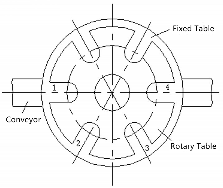
Schematic Diagram of Rotary Filling Machines
In this system, the conveyor belt is used to continuously convey the containers, and the containers and bottles are evenly distributed on the conveyor belt at equal intervals. After entering the workstation, the predetermined working procedures are processed in each workstation in turn. After all the working procedures are completed, the containers are output to the designated position by the conveyor belt. This design process is closely related, with reasonable process intervals and uniform arrangement, which can effectively solve the problem of container bottles piling up on the workbench. This system is driven by the electric motor, and through the selection of mechanism, the transmission and conversion of motion can be realized to achieve automation.
2. Selection of Institutions
In order to ensure the good realization of each-part functions of the filling machine, it is necessary to select a reasonable mechanism to transfer and convert the motion. The following mechanism design is made for each subsystem of the filling machine.
(1) The rotary system of the filling machine adopts the grooved wheel mechanism, which can accurately realize the intermittent rotary motion, ensuring the coordination between the mechanisms. It can also ensure that the containers and bottles can stably enter the next station, which is not easy to topple and has a low failure rate.
(2) The sealing and capping system of the filling machine adopts the connecting rod mechanism. Because the connecting rod mechanism has the characteristics of simple and reliable structure, large transmission load, long transmission distance and quick return movement, it can make the whole structure of the filling machine simple, high in working efficiency and not prone to failure.
(3) The clamping and positioning of the filling machine adopt the cam mechanism, which can make the follower get any desired movement, and has a simple structure, compact structure and convenient design, ensuring accurate positioning, and strong coordination ability among the mechanisms. The clamping cam can be combined with the groove of the rotary table to clamp the container bottle, and there will be no failures such as toppling and falling off the workbench when rotating. Although the cam mechanism is in high-pair contact, because of the small volume and lightweight of the container bottle, the required clamping force is small, and the rotating speed of the filling machine is low. Therefore, if the heat generated during long-term continuous work is small, the structure is not easy to wear and tear, and it can work continuously and stably for a long time.
(4) The filling system of the filling machine adopts the cam mechanism, which can ensure smooth filling. The liquid is not easy to spill out of the container bottle, and the filling can be realized quantitatively, without any problems such as under-filling or overflow.
3. Mechanical Motion and Working Principles
According to the filling principle, the functional breakdown and the mechanism, the mechanical motion diagram of the rotary filling machine can be drawn as follows. The structure and working principle can be seen from the mechanical motion diagram of the rotary filling machine, and the working principle is as follows:
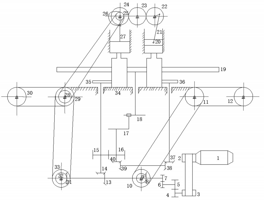
(1) Motor 1 is transmitted to pulley 3 through pulley 2. 3 is transmitted to gear 4 through a shaft. 4 is transmitted to gear 5. 5 is transmitted to gear 6 and 6 is transmitted to gear 7 through a shaft, thus forming three-stage transmission.
(2)7 is transmitted to bevel gear 31 through a shaft. 31 is transmitted to bevel gear 32. 32 is transmitted to coaxial pulley 33, and 33 is transmitted to pulleys 29. 29 and pulley 30 constitute an input mechanism to convey containers together.
(3)7 is transmitted to bevel gear 13 through the shaft, and 13 is transmitted to bevel gear 14. 14 is transmitted to clamping cams 35 through the shaft. 35 and workbench grooves together complete positioning and clamping actions.
(4) pulley 29 is transmitted to the coaxial pulley 28, and pulley 28 is transmitted to pulley 25. Pulley 25 is transmitted to the coaxial cams 26, 26 to push the piston pushers 27, 27 to complete the filling action.
(5) The bevel gear 14 is transmitted to gear 15 through the shaft, and gear 15 is transmitted to gear 16. The gear 16 is transmitted to the coaxial driving dial 17, and the driving dial 17 is transmitted to the driven grooved wheels 18. The driven grooved wheels 18 drive the workbench 19 to rotate, realizing intermittent movement, and transfer the container to the next station.
(6) The gear 16 is transmitted to the coaxial bevel gears 40, 40 to the bevel gears 39, 39 to the coaxial bevel gears 38, 38 to the bevel gears 37, 37 to the coaxial clamping cams 36, 36 and the workbench groove to complete the positioning and clamping action together.
(7) The pulley 25 is transmitted to the coaxial gear 24. 24 is transmitted to the gear 23. 23 is transmitted to gear 22, and 22 is transmitted to the connecting rods 21, 21 to push the bottle stopper 20 to reciprocate and complete the sealing action.
(8) Gear 7 is transmitted to coaxial gear 8, which is transmitted to bevel gear 9. 9 is transmitted to coaxial pulley 10. 10 is transmitted to pulley 11, and pulley 11 and pulley 12 together complete the output action of the filled container.
4. Distribution of Transmission Ratio
The mechanisms required for the rotary filling machine to complete the above movement are as follows: the intermittent movement mechanism of the rotary table is a grooved wheel mechanism, a crank-slider mechanism for sealing, a cam mechanism for filling, a cam mechanism for positioning and clamping, and a pulley mechanism for the input and output of container bottles. The conveyor belt is driven by a synchronous belt. The working surface of the belt is made into a tooth shape, and the hub surface of the pulley is also made into a corresponding tooth shape. This kind of belt drive has minimal deformation after being loaded. The pitch of the toothed belt is basically unchanged, and the transmission ratio is constant and accurate. The toothed belt is thin and light, which can be used in high-speed occasions. The linear speed can reach 40 m/s. The transmission ratio can reach 10, and the transmission efficiency can reach 98%. In order to make the filling machine more efficient, the filling machine is driven by the electric motor to realize automation. If the rotary table diameter is set to 600mm and a three-phase asynchronous motor is used, the rotating speed of the motor is required to be 1440rpm and the rated power is 4kW. After deceleration, the filling speed can be 10 bottles/min. Because of the high speed of the motor, the transmission system should be designed to reduce the speed. The transmission system adopts a three-stage reduction mechanism. The first stage is belt drive, and the second and third stages are gear drive. In order to make the transmission components smaller in size and compact in structure, the transmission ratio principle of "first small and then big" is adopted. First, calculate the total transmission ratio, and then allocate the transmission ratios at all levels. Calculate the total transmission ratio:

Among them, i0 is always the total transmission ratio of the transmission deceleration system; i1 is the transmission ratio adopted for the first-stage deceleration; i2 is the transmission ratio adopted by the second-stage transmission; i3 is the transmission ratio adopted for the third-stage deceleration; n0 is the rotational speed of motor 1; n1 is the rotation speed of pulley 3; n2 is the rotational speed of gear 5; n3 is the rotation speed of gear 7. Distribution of transmission ratios at all levels: if i1 = 4, i2 = i3 = 6, then i0 = 144. After three-stage deceleration, the rotating speed of the shaft connected with gear 7 is reduced to 10rpm, and the meshing transmission ratio of bevel gear is 1, so that the rotating speed of the rotary table is 10rpm, thus achieving the filling speed of 10rpm. The meshing transmission ratios of other gears and bevel gears are all 1.
5. Gear Parameter Design
Gear mechanism plays an important role in the movement transmission process of rotary filling machines. In order to ensure the smooth transmission of the whole movement, detailed gear parameters are designed. Parameters of gears 4 and 6 are consistent; Parameters of gears 5 and 7 are consistent; Parameters of wheels 15 and 16 are consistent; Parameters of bevel gears 8, 9, 13, 14, 31, 32, 37, 38, 39 and 40 are consistent (as shown below). The design of the transmission shaft can determine the minimum diameter of the transmission shaft according to the external force on the transmission shaft, and then determine the diameter of the transmission shaft according to the actual situation. This system is designed in principle, and the specific parameters can be determined by referring to the Mechanical Design Manual according to the actual situation.
Parameters of spur gears:
Tooth number z, gear 4,6, z =15; Gear 5, 7, z =90; Gears 15, 16, z =40
Modulus M, gear 4,6, m = 1; Gear 5, 7, m = 1; Gears 15, 16, m =1
Pressure angle a, gear 4,6, a = 20 ˚; Gear 5, 7, a = 20 ˚; Gears 15, 16, a =20˚
Width b, gear 4,6, 5 5mm; Gear 5, 7, b =5mm; Gears 15, 16, b =5mm
Parameters of bevel gears:
Bevel gears 8, 9, 13, 14, 31, 32, 37, 38, 39 and 40: modulus 2, tooth number 20, pressure angle 20 ˚, face width 12mm, hub diameter 75mm, mounting distance 10mm and nominal shaft diameter 10mm.
6. Motion Cycle of Rotary Filling Machines
The actuators of the structure must coordinate with each other in action. If the coordination relationship is destroyed, the mechanical structure will not only fail to complete the expected tasks but even damage the mechanical equipment. In order to ensure the coordination and cooperation between the actuators of the mechanical structure when working, a motion cycle diagram (as shown below) is compiled to show the coordination and cooperation between the actuators in a working cycle of the machine. The working process of the motion diagram is that when the filling machine works, the input conveyor belt and the output conveyor belt are constantly rotating to convey the container. When the workbench is not rotating, each station carries out processing to complete the established process. When the workbench does not rotate, the container bottle at station 2 is clamped to complete the filling action. The container bottle at station 3 is clamped to complete the sealing action. When the canning and sealing processes are completed and the mechanism returns, the clamping cam rotates without clamping the container bottle. At this time, the workbench rotates, and the processed container bottles are sent to the next station for processing.
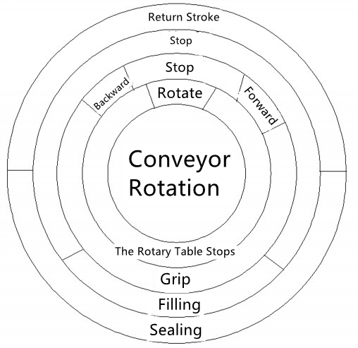
Motion Cycle of Rotary Filling Machines
Modeling and Simulation Analysis of Rotary Filling Machines
1. Modeling the Whole Rotary Filling Machine with Software
Solidworks software is used to model the rotary filling machine based on the principle described in this article (as shown below), which can clearly see the appearance, movement principle and the assembly relationship between various mechanisms, and provide the basis for processing and manufacturing parts and debugging products.
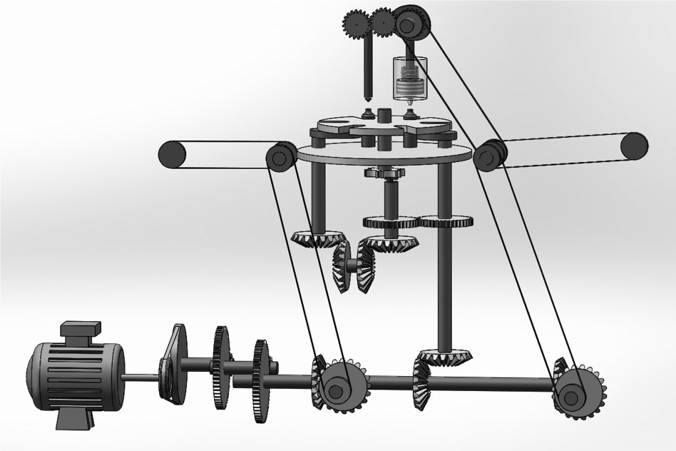
Schematic Diagram of Internal Mechanism
2. Motion Simulation of Filling Mechanism of Rotary Filling Machines
The filling mechanism adopts a cam mechanism, which can finish the filling task of the beverage more accurately. Because the filling requires high precision and is important in the whole rotary filling machine, the contour design and motion analysis of the filling cam are needed. The motion law of the filling cam is simulated by software for qualitative analysis. Basic working parameters of rotary filling machine in the simulation set the number as follows:
(1) Container height h = 200mm
(2) The range of motion of the piston s = 40mm
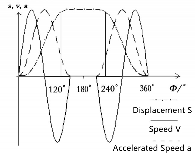
(3) The total length of the push rod and piston l = 105mm, and then select the basic parameters of cam: ① Radius of base circle R0 = 45 mm; ② Roller radius RT = 0 mm; ③ stroke s = 40mm; ④ Push angle δ 0 = 120°; ⑤ Return angle δ = 120°; ⑥ Near angle of repose δ01 = 60°; ⑦ Distant angle of repose δ02 = 60°; ⑧ The maximum pressure angle of lift αmax 01 = 31.454°; ⑨ The maximum return pressure angle αmax 02 = 31.454°; ⑩ The cycloidal motion law without flexible impact and rigid impact is selected for the push and return of cam motion, and the static motion law is adopted at far rest and near rest.
It can be seen from the motion cycle diagram and the displacement line diagram below that when the shaft rotates between 0° and 120°, the container bottle is in a static state, while the cam is in a pushing state, so that the liquid can be filled. When the shaft rotates between 120° and 140°, the rotary table rotates, and the filled container bottle enters the next station. During this period, the piston is at the bottom of the liquid storage cup and remains stationary, blocking the filling channel and preventing the liquid from flowing out. When the shaft rotates between 240° to 360°, the rotary table rotates. The next empty container bottle enters the filling station. The cam is in the return state. The liquid filling is completed, and one cycle of work is completed. From the velocity diagram and acceleration diagram, it can be seen that the velocity and acceleration change continuously. There is no flexible impact and rigid impact, and the movement is stable, which fully meets the design requirements.
Motion Curve of Cam
3. Motion Simulation of Sealing Gland Mechanism
The sealing cover adopts the crank-slider mechanism, which has the quick-return characteristic and can ensure that the sealing operation can be completed quickly and accurately. The capping mechanism plays an important role in the rotary filling machine, so detailed design and motion analysis are carried out. Set the initial parameters of gear and crank installation height and speed:
(1) The installation height of gear and crank is 400mm.
(2) The speed of gear and crank is 10rpm.
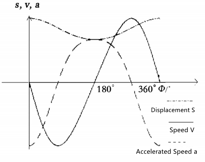
According to the set initial parameters, it can be obtained that the crank length L1 = 30mm; The length of connecting rod L2 = 150mm; Travel of the gland slider s = 60mm. The outline size and qualitative motion simulation of the crank slider are shown below. The displacement of the crank slider is a sinusoidal motion law, which can quickly complete the sealing action when the container bottle filled with liquid arrives at the sealing station, and when the container bottle enters the next station, the slider returns to the original position to complete a cycle of motion. From the velocity diagram and acceleration diagram, it can be seen that both velocity and acceleration are sinusoidal motion laws. It can be seen that the deviation between velocity and acceleration is small, accurate, and the impact is small, which can ensure that the workpiece wear is small. The sealing action can be well completed, which meets the design requirements.
Motion Curve of Crank-slider Mechanism
Conclusion
By analyzing the working principle, structural characteristics and shortcomings of existing filling machines in the market, this topic designed a new type of fully automatic rotary filling machine structure and motion scheme, and analyzed its working principle and function. The main contents are as follows:
(1) Based on the analysis of process actions, the reasonable design of the motion mechanism involved in each process action is made, such as the way of container transportation, positioning and clamping, intermittent indexing of rotary table and quantitative filling, etc.
(2) In the selection of actuator and the determination of motion scheme, the intermittent mechanism and quantitative filling mechanism of the rotary table are studied emphatically. By comparing their advantages and disadvantages, the type selection is reasonable and correct, so as to ensure that the reasonable mechanism is adopted and the overall work efficiency is higher.
(3) Modeling and kinematics simulation of the whole filling machine can make the movements of each mechanism coordinate with each other and run smoothly, laying a good foundation for subsequent processing, manufacturing, popularization and application. Compared with the existing filling machines in the market, the filling machine designed in this article has the advantages of accurate positioning, stable filling, simple mechanism, low manufacturing cost, high degree of automation and high operating efficiency, and is suitable for large-scale popularization and application.
